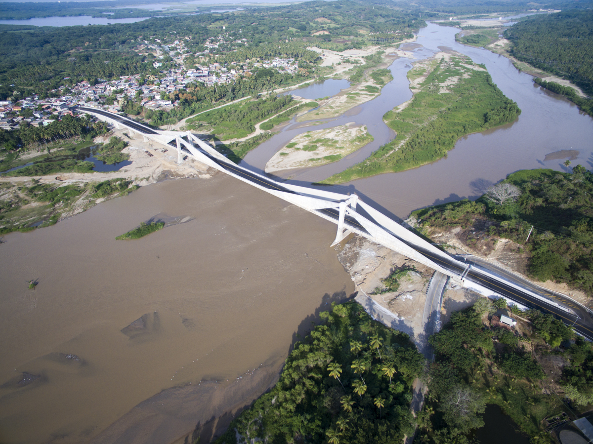
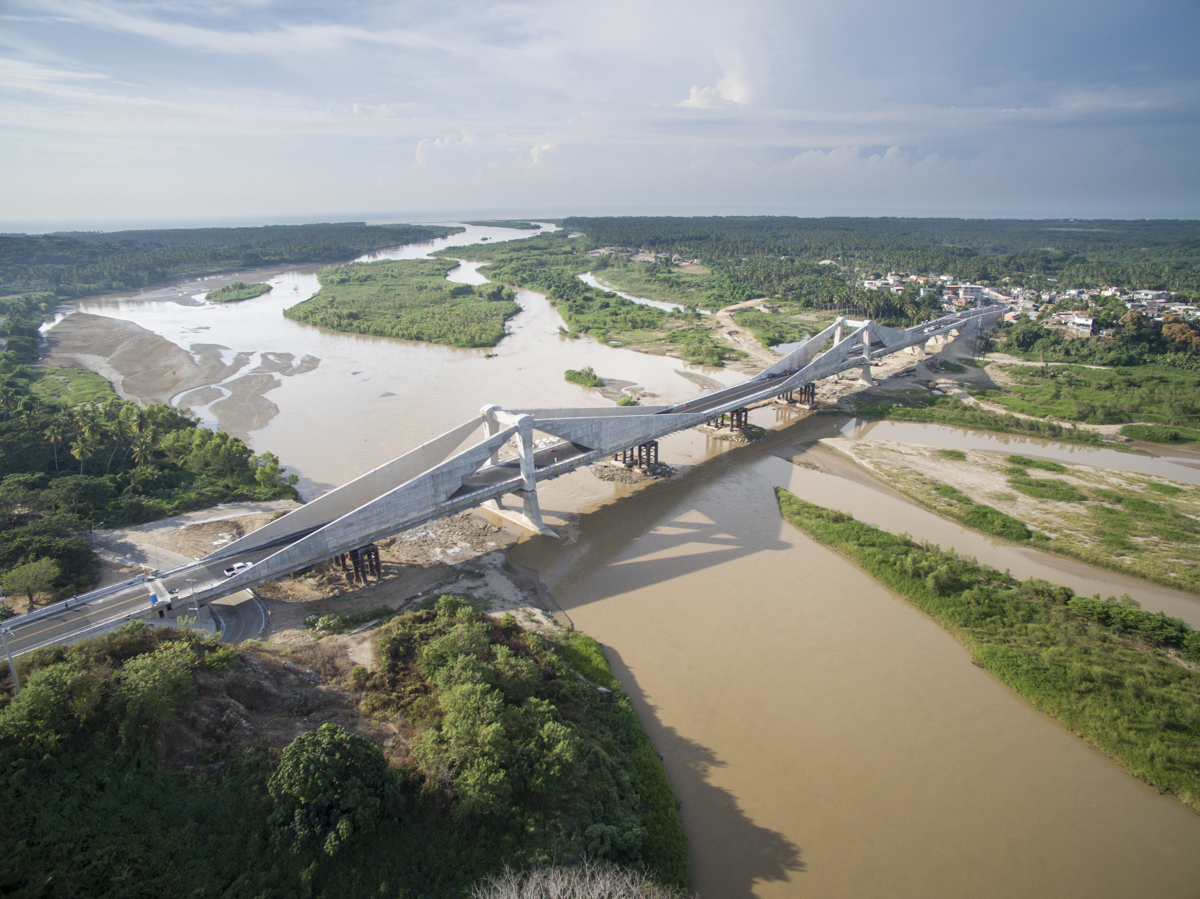
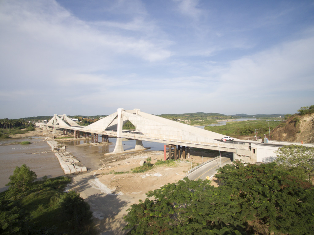
The Barra Vieja Bridge is located in Lomas de Chapultepec, to the south of Acapulco, over the Papagayo river mouth in the State of Guerrero, Mexico. It is in the same location as the bridge destroyed by floods in September 2013, as a result of tropical storm “Manuel”.
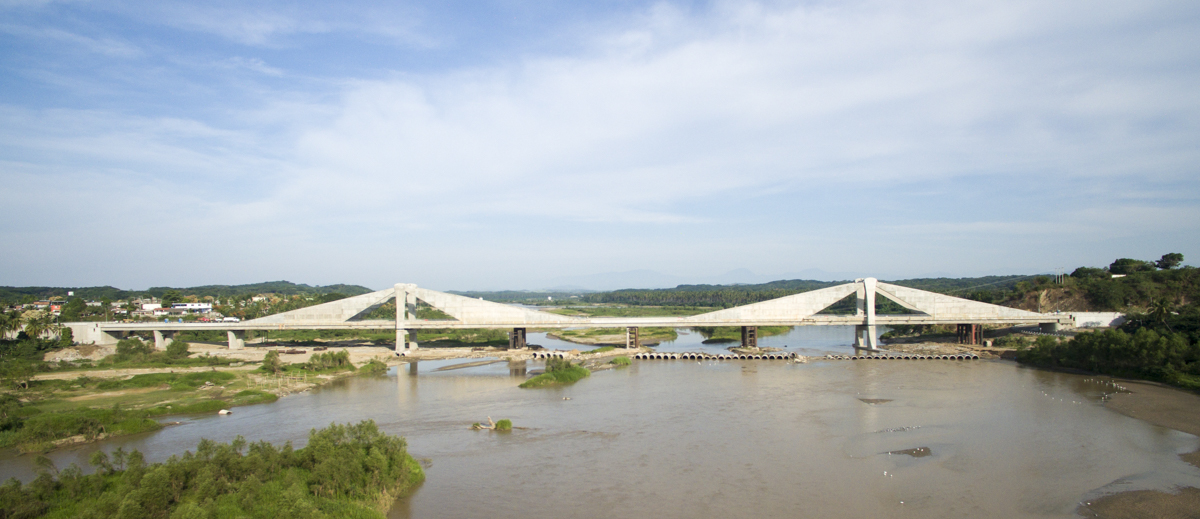
The designed structure is a concrete sail bridge with a main span of 220 m. The total length of the bridge is 470 m, with five spans of 30+40+90+220+90 m. The structure was designed without piers in the center of the river bed, given that the foundations would be unstable due to possible soil liquefaction caused by seismic activity, which is highly common in the area.
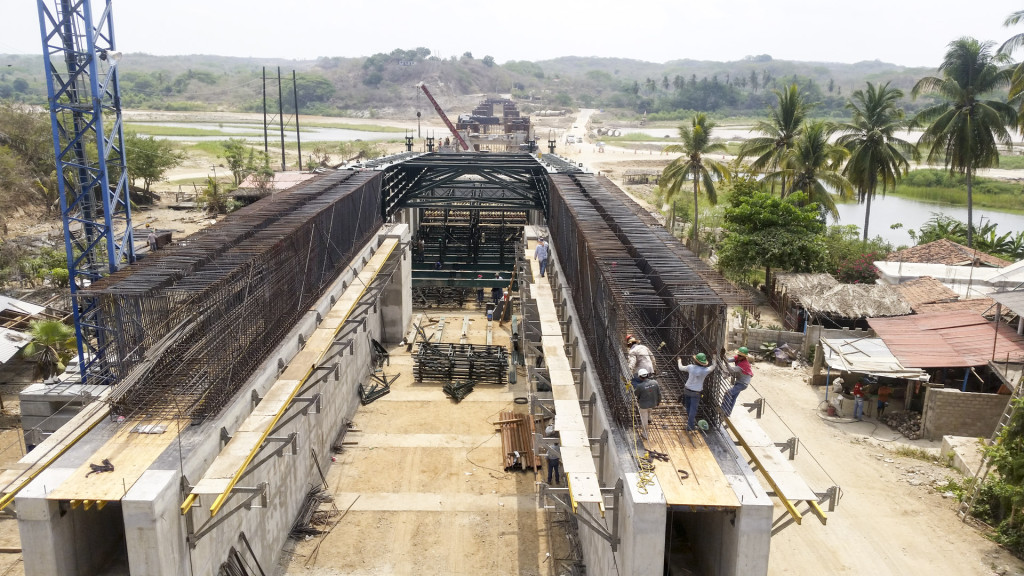
The bridge deck is comprised of two longitudinal box girders connected by ribs every 5 m. It has a width of 15.05 m and a constant depth of 3.10 m. The upper slab has a thickness of 0.28 m.
The stay system is comprised of 28 cables that are embedded into the concrete sails. The cables use pre-stressing technology rather than stays, with the associated savings in costs.
The sails are triangular-shaped, with a variable thickness ranging from 1.48 m at the top of the towers to 0.36 m at the deck. They are set out 30 m from each tower and continue for a further 56.3 m. The height of the towers is 17 m.
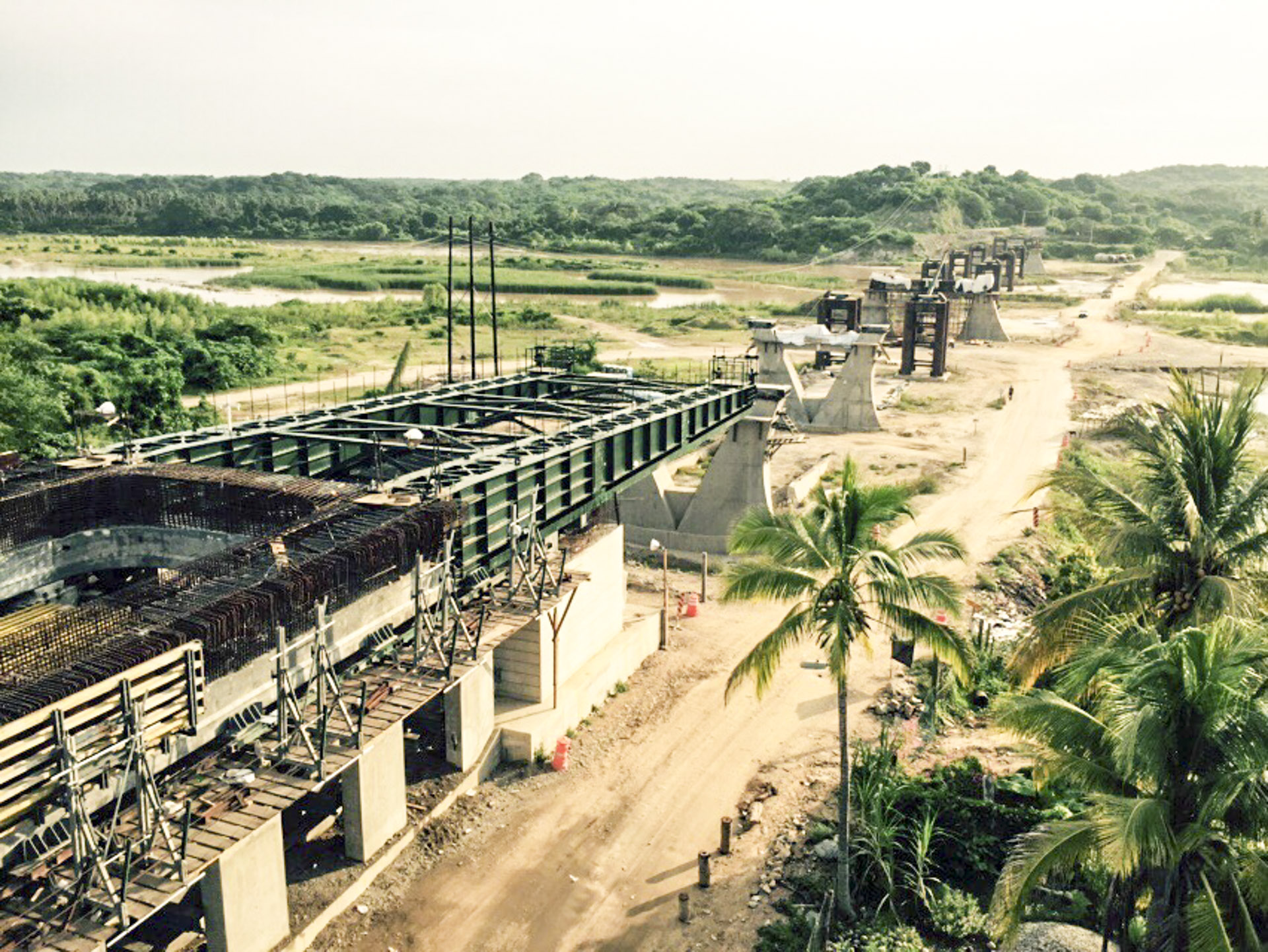
One of the unique features of the project is its construction process. Initially, there was very little time to build the bridge and it was decided to push the deck out and then construct the upper sections of the towers and place the stays and concrete them in in the final phase. This process made it necessary to place five 90 m provisional metallic piers in the spans 50 m from the towers and in the central span every 55 m.
Given the type of soil, all the foundations were constructed using 1.50 m diameter piles for abutment 1, piers and towers, whereas 1.20 m diameter piles were used for the temporary piers.
One of the major issues studied in the project was how to overcome the seismic effects which, as mentioned, are frequent in the area mainly due to the existing soil characteristics. In this project, two longitudinal dampers were placed in abutment 1, each of 6000 kNs/m and transversal dampers of 2000 kNs/m in pier 2 and buffer 6, 3000 kNs/m in abutment 1 and pier 3 and of 6000 kNs/m in the towers.
The maximum designed displacement of the dampers is ± 290 mm in the longitudinal direction and ±370 mm in the transverse direction. As the dampers do not have recentering capability, we decided to use pendulum bearings for all supports, except abutment 6, where neoprene-teflon bearings are used.


