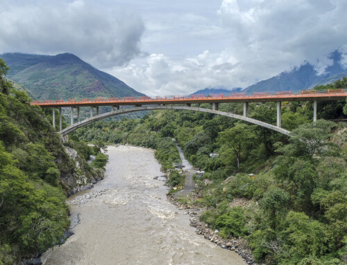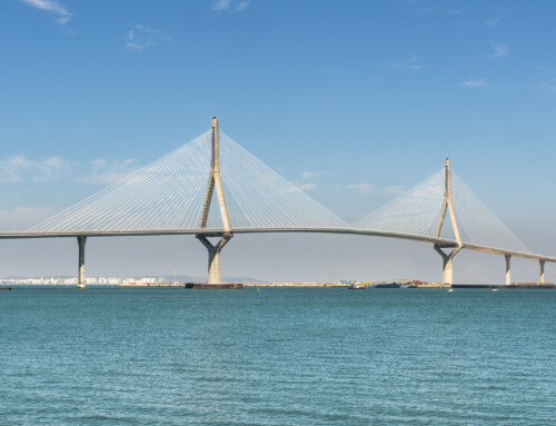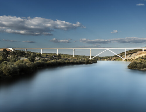


Leonardo Bridge over the Arno river Arezzo. Italia. 2014.
The bridge over the Arno River, a CFCSL project, is located on the road linking the municipalities of Terranova Bracciolini, San Giovanni Valdarno and Montevarchi. Arezzo. Italia.
From the beginning of the project, which was the subject of an international competition, the design of a unique bridge adapted to the environment and visible both from the Autopista del Sol and from a large part of the municipalities mentioned above has been a priority. As in any project work, the solution finally chosen responds to a process of successive approaches in which the different factors involved have been taken into account: structural, constructive, environmental and economic. The solution developed corresponds to a closer fit to the terrain profile of solution 1 presented in the tender offer for the project. It is a bridge with a total length of 495m. It has two main spans over the Arno river with spans of 110 and 77 m, with side spans of 30, 25 and 48 m. With a distribution of 5.0+3×30.00+110.0+77.0+48.0+4×30.0+25.0 m. This span distribution has been conditioned by several factors.
On the one hand, the Arno riverbed in the area of the bridge is poorly defined and does not need to bridge the full width between the flood banks. For this reason, one of the piers (Pile P-5) has been placed in the riverbed on a fairly stable and well-defined island; Piles P-4 and P-6 delimit the river’s flood channel; The crossing of the Autopista del Sol is made with a 48.0 m span so as not to hinder its service during construction and to allow for its future expansion.
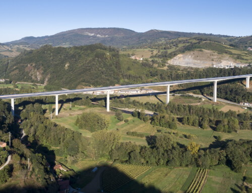
On the left bank, the spans have 30.0 m spans except for the extreme span which has 25.0 m in order to achieve an adequate structural compensation. With these spans a diaphanous and transparent area is achieved both from the hydraulic and landscape point of view, achieving a maximum height of the E-1 abutment of 5.80 m.
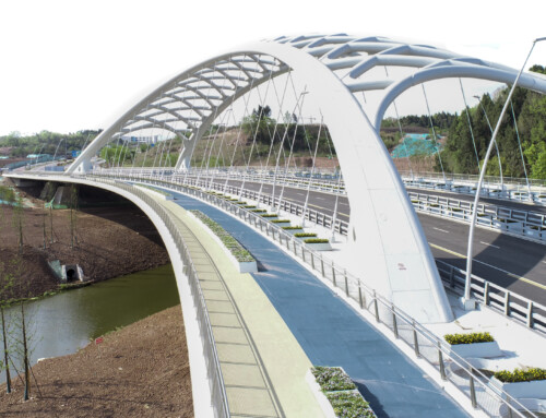
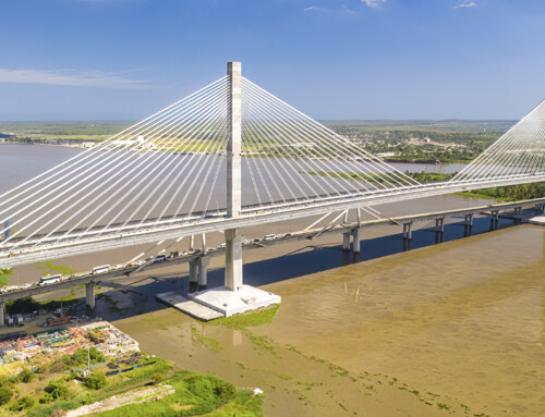
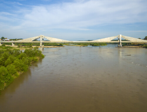
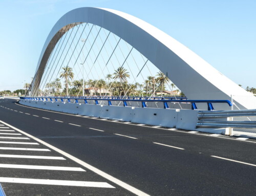
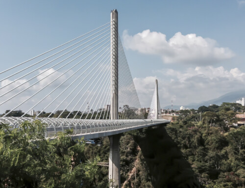
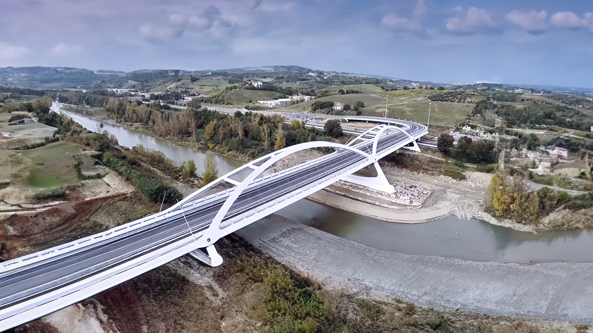
On the right bank after the highway crossing, the deck is extended with 30 and 25.0 m spans to achieve a reduced abutment height of 5.00 m so that the access embankment has a limited height, given the geotechnical conditions of the area. The main spans are formed by two upper arches located on two inclined planes joined in the keystone area and two intermediate diaphragms. These arches are linked to the deck by means of tie rods and lower ribs located every 5 m.
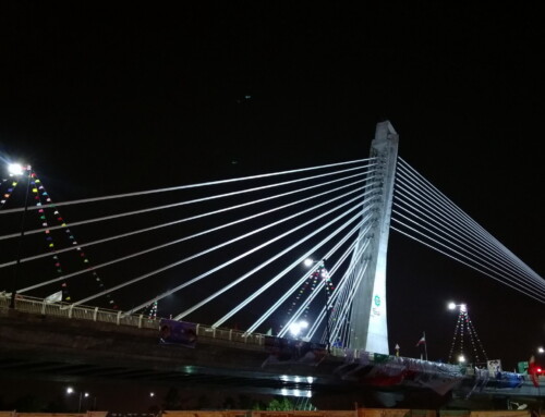
The effect of the two inclined arches, one prolonging the other, provides both drivers and pedestrians with an important reference point at the entrance to the town of Montevarchi. This enveloping arrangement of the structure, on the other hand, does not produce any visual or landscape interruption to the user due to the large separation of the structure, on the one hand, and of the suspenders, on the other;
The cross section consists of two 3.0 m wide pedestrian areas for pedestrians and cyclists, two 1.50 m wide shoulders and two 3.75 m wide roadways. The deck has three types of sections, adapted to the ranges of spans and typologies, in both cases in mixed concrete-steel section. In the arch area (and the two adjacent spans) they are formed by transverse ribs every 5.0 m and two lateral caissons of 1.90 m edge and 0.80 m width with variable thicknesses that act as lower suspenders of the arches.
The concrete deck has a width of 18.00 m although the requirements for connection to the arches necessitate a total width of 22.60 m. In the two spans adjacent to the arches with respective spans of 30 and 48 m, the deck has a section composed of side caissons with a variable edge and transverse beams as in the arch spans and, simultaneously, a caisson as in the access spans. In this way, a formal transition is achieved between the two types of deck and at the same time increases the resistant capacity of the span over the freeway, of span range and with a strict clearance gauge.
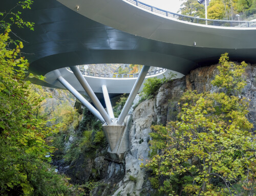
The deck section in the rest of the access spans is a tricellular box section with 2 vertical cores and 2 inclined cores with a total depth of 1.40 m. The total width is 18.00 m except in the last 2 spans that undergo a progressive widening to 21.58 m in abutment E-2. The total width is 18.00 m except in the last 2 sections, which undergo a progressive widening up to 21.58 m in abutment E-2. In both sections, the reinforced concrete slab has a total thickness of 0.25 m formed by a 0.06 m precast slab and a 0.19 m in-situ concrete slab. The piles on which the deck with the cross ribbed section rests have a trapezoidal geometry in prolongation with the planes of the arches with variable dimensions created by three circumferential arches in the lower brace.
The foundation is made by means of 1.20 m piles in variable number. The piles on which the deck with the box section rests are formed by a diaphragm with a constant longitudinal dimension equal to 1.20 m and variable transversal dimension from 4.0 m at the bottom to 6.5 m at the top in a curved transition with a radius of 18.85 m. These piles are founded on 5 piles of 1.20 m diameter. The pile caps are square, 7.30 m on each side and 2.50 m high. The support devices will be of neoprene-teflon in box and neoprene-bonded with a variable load capacity from 300 to 1900 Mp. The abutments are formed by a front wall of 1.20 m thick founded on piles of 1.20 m in diameter and 2 fins of 5.80 m in length in the case of abutment E-1 and lateral walls that can be founded with footings in the case of abutment E-2.