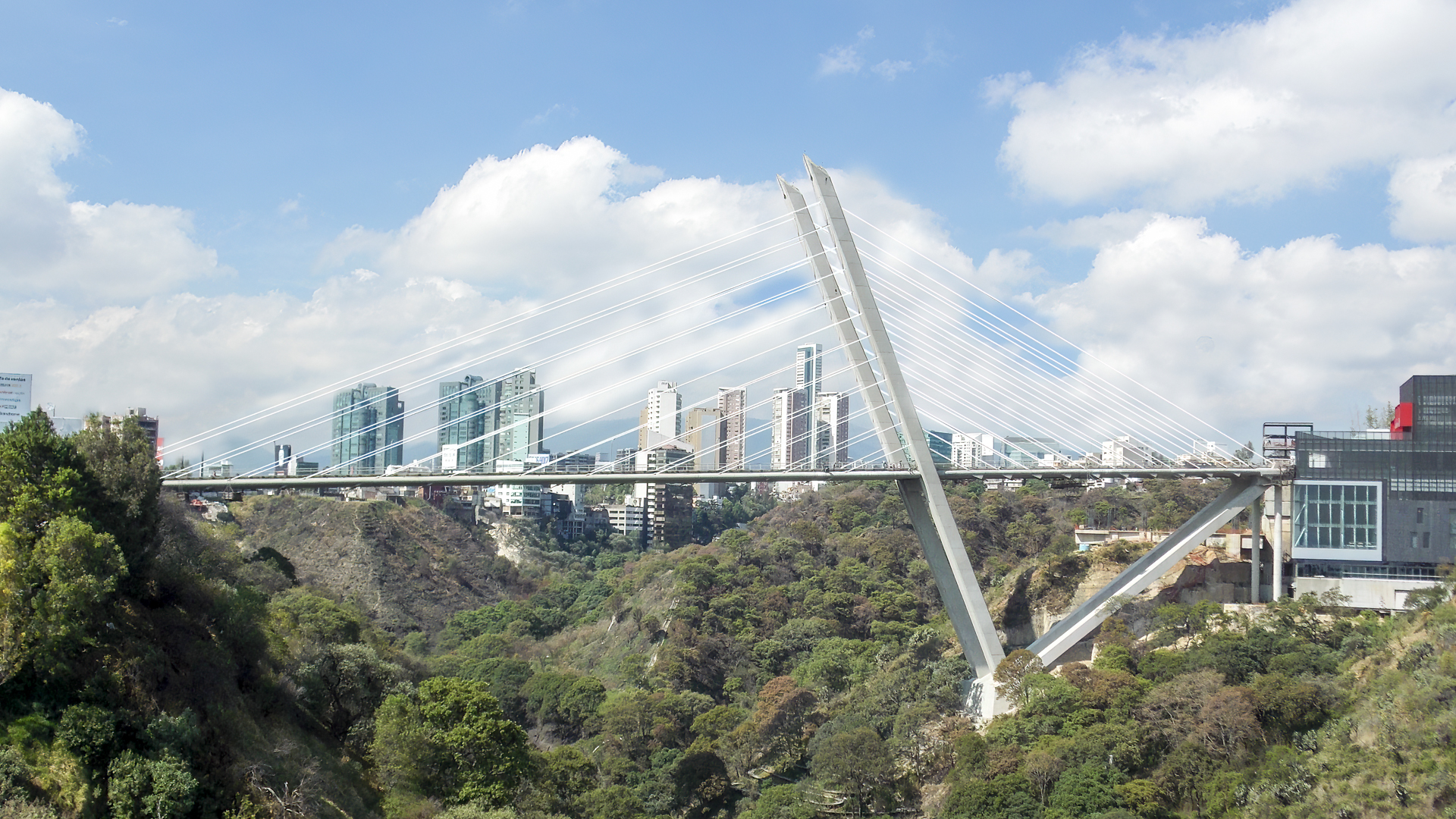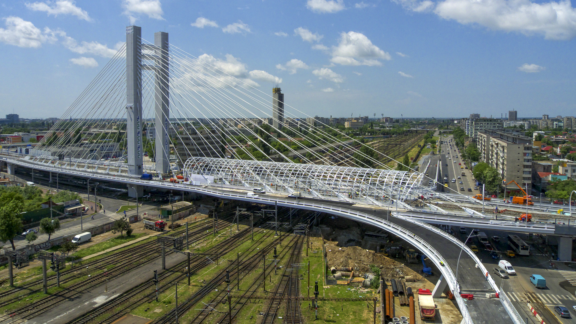
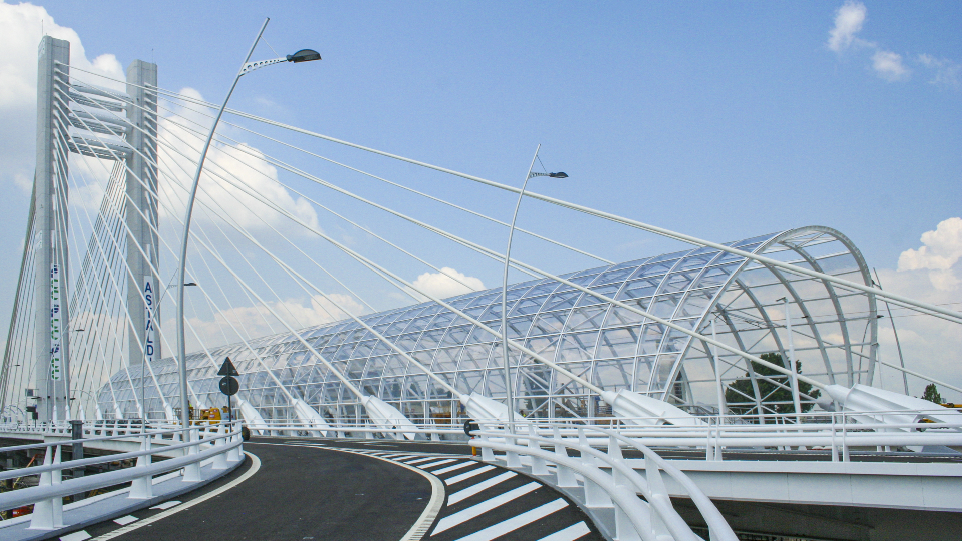
Basarab Bridge Bucarest. Rumania. 2012.
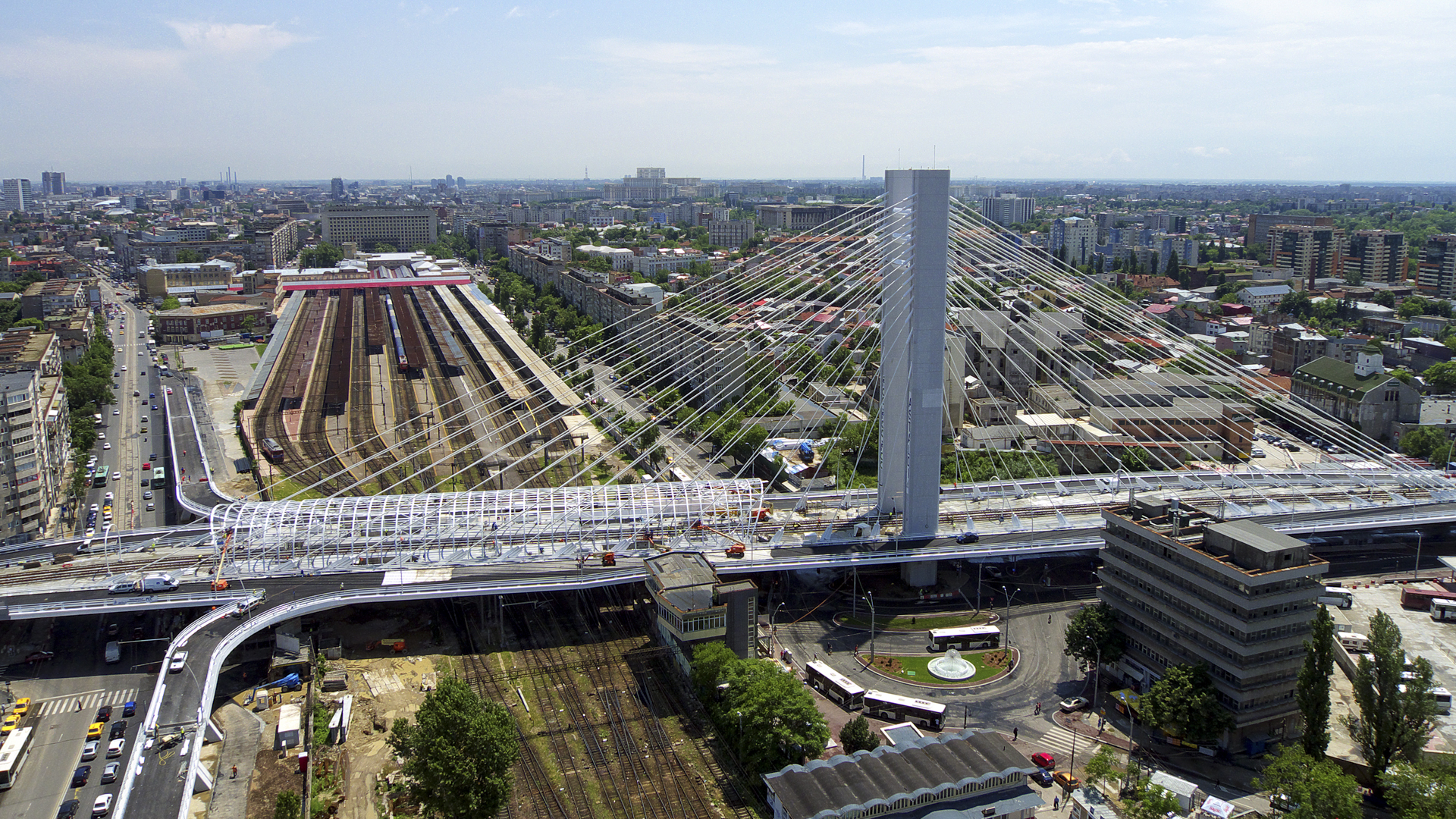
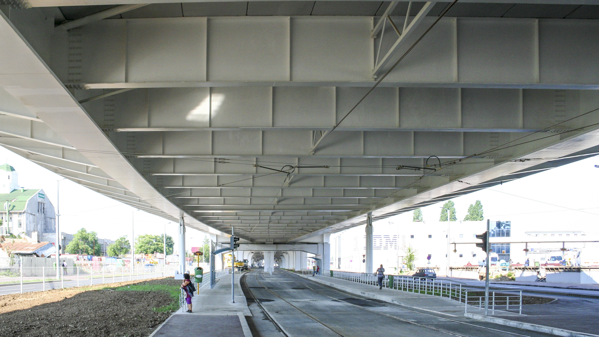
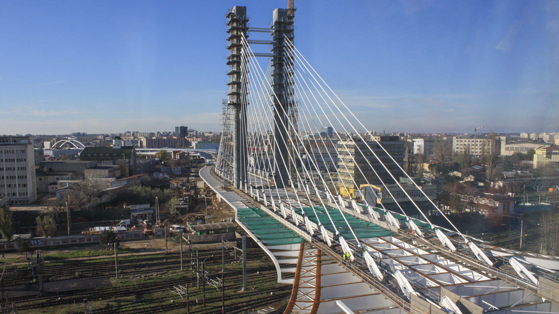
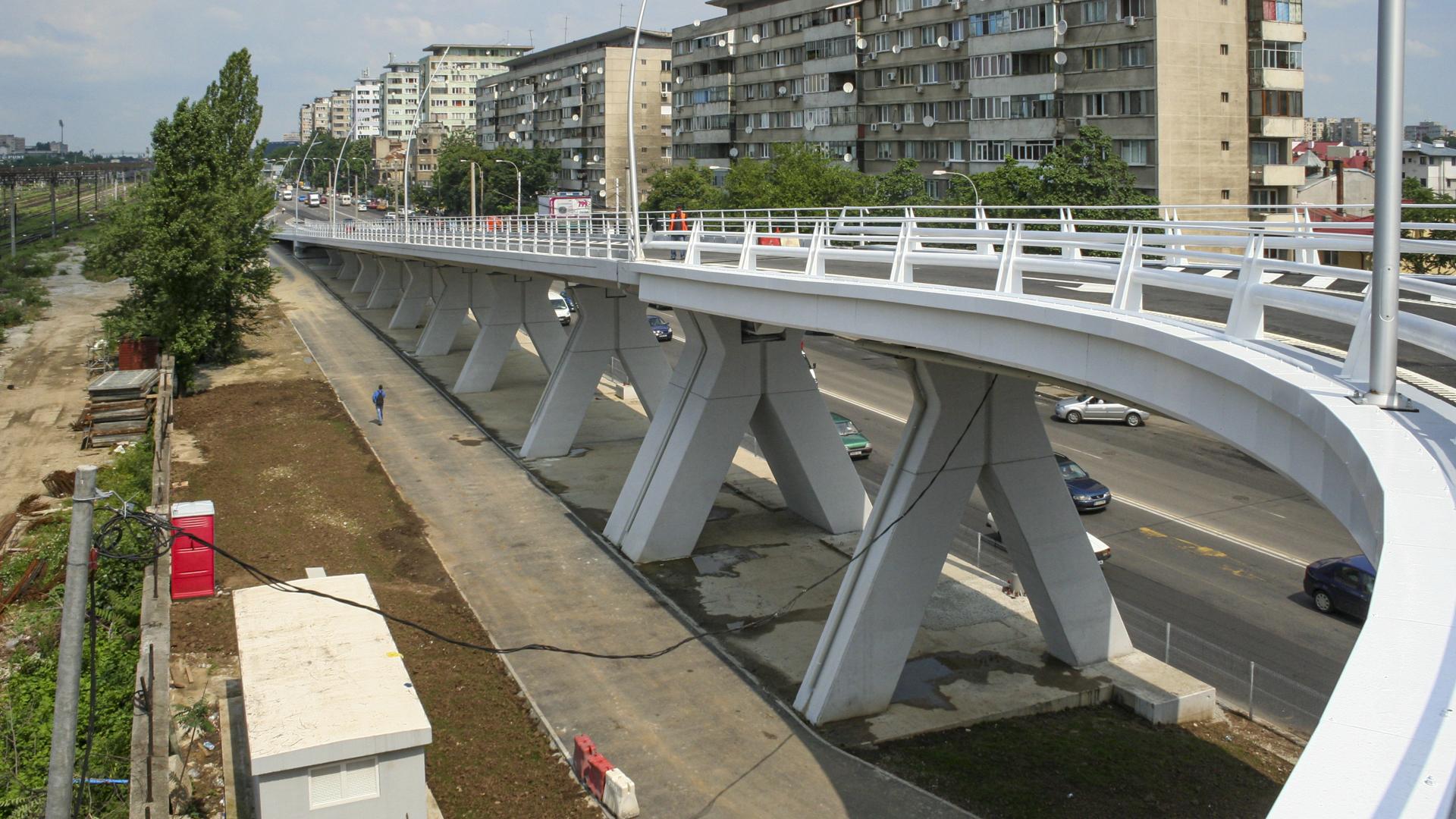
The Basarab viaduct jumps over the railway tracks at the Bucharest railway station, supporting a motorway, a tramway line and a railway-tramway interchange station. The general structure of the bridge consists of a main span where the tramway is located in the centre, and in a localised area, the station with its ramp and stairway accesses and the two traffic lanes, each with two lanes on either side of the tramway. It is a cable-stayed bridge from a single tower with spans of 56.5m+75m+168+36m+30m. The 7.50 m wide access ramps hang from the main span that spans the track bed, which continue in prestressed concrete approaches and small spans. The width of the bridge varies from 37.88m to 43.38m. It is a complex bridge for the following reasons: 1 – It has an irregular plan that is not very symmetrical, both longitudinally and transversally, with access ramps entering and leaving the lintel at the bottom of the bridge.
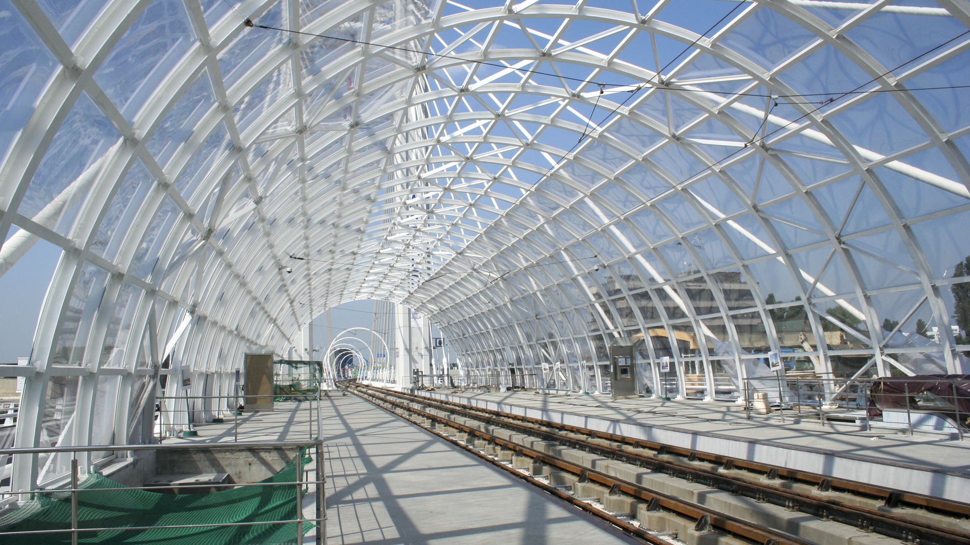
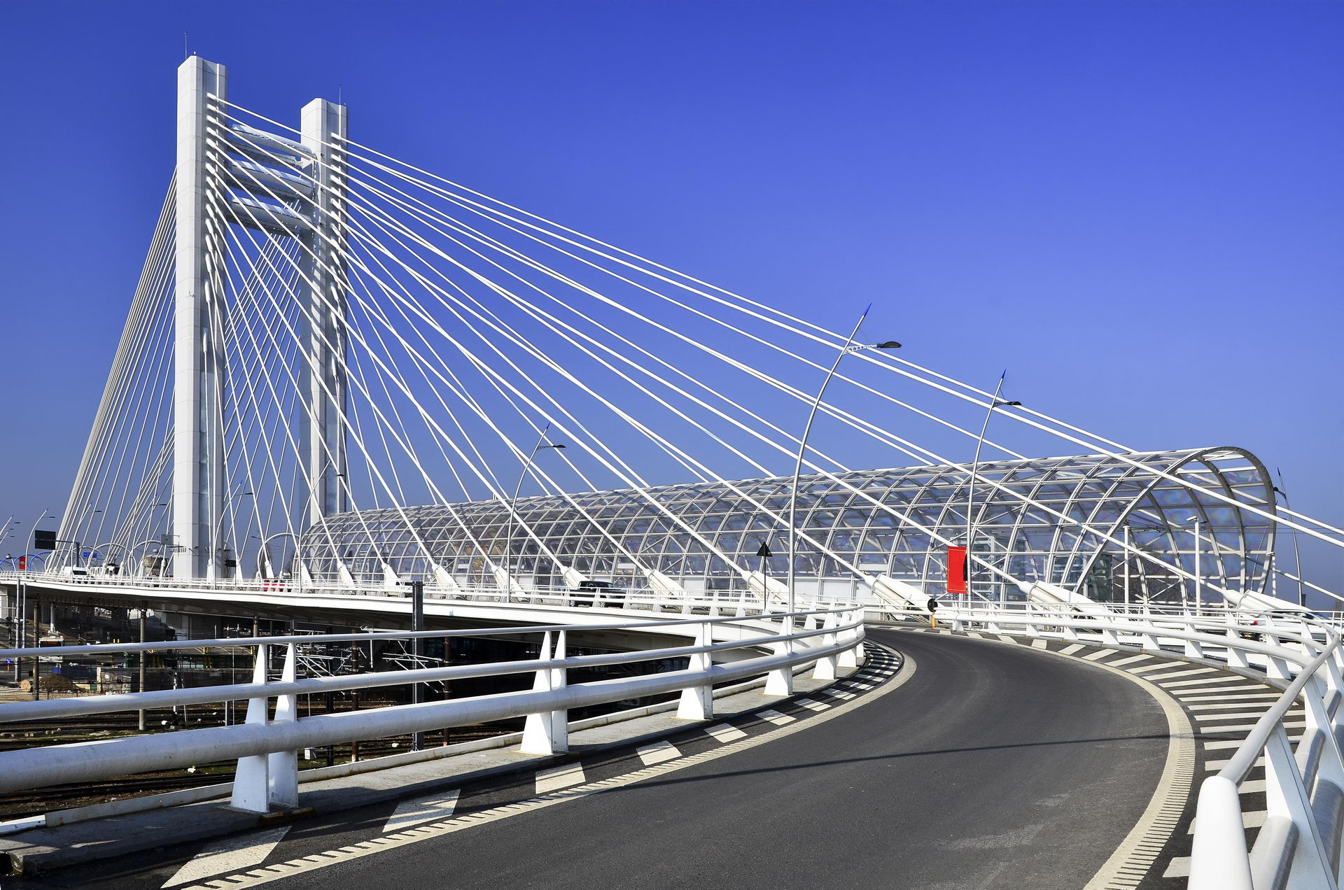
2 – It is a large bridge, with a main span of 168 m and a single tower which would be equivalent to a twin-tower bridge with a span of 340 m. 3 – It is installed in a seismic zone. 4 – It has two types of load, road and tramway, as well as supporting a station in the centre with its roof and its accesses from the street, which pierce the lintel. The 168 m long deck is supported by 15 pairs of braces anchored to the deck, every 10 m on the two main longitudinal beams and on the tower. The lintel is the most morphologically complicated part of the bridge. To resolve it, a mixed lintel was used, consisting of two 2.5 m high longitudinal double T beams, arranged in the median separating the tramway from the carriageway. It also consists of a transversal mesh of beams arranged every 5 m. with a 2.00 m edge in the part located between the two longitudinal beams, whose separation is about 20 m, and a variable edge up to 0.30 m at the end of the cantilever, which is about 10 m long.
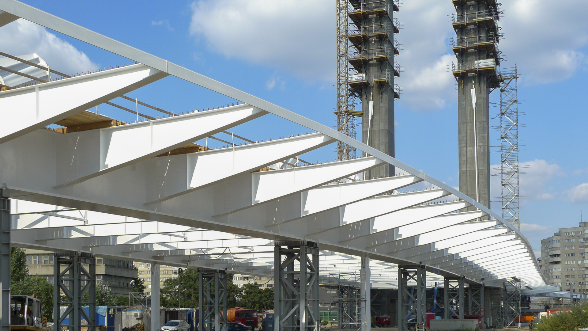
span and has an end closing beam. The top concrete slab is 0.35 m thick. The two longitudinal beams are never interrupted, but the cross beams are cut to make way for stairs and lift. In this case, two new longitudinal beams must be placed between the last uninterrupted transverse beams and the floors and stairs must be developed between them. The box girders supporting the transverse ramps penetrate the lintel with a variable-edged metal box section up to the main load-bearing core. The tower has a height of 80 m above the deck and consists of two 6×4.6 m vertical shafts chamfered at the corners. They are braced together by a 5×1.5 m prestressed concrete beam and 3 bi-articulated metal braces at the top. It is founded by 52 piles of 1.8 m in diameter. The tie-rod anchors transfer their load through the pile by means of transverse prestressing.
All the metal sections of the bridge are supported on temporary supports, except for the metal part located on the track bed, which is pushed. Once the entire metal deck has been built, an initial stressing load is applied to the stay cables in order to be able to unbuckle them. The slab is then concreted on the stay cables in symmetrical sections with respect to the tower so that the increase in axial force in the stay cables acts on the entire section, and to compensate for the tower. Once the entire slab has been concreted, a second phase of tensioning is applied to the stay cables so that at the end of construction they have the load to compensate for both their own weight and the weights of the station and platforms. Finally, the station and platforms are built and the dead load is placed.