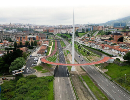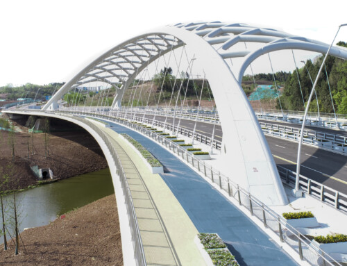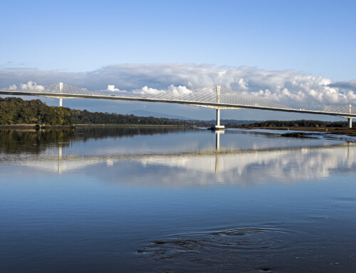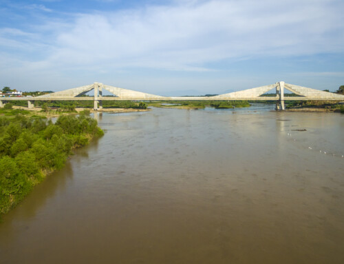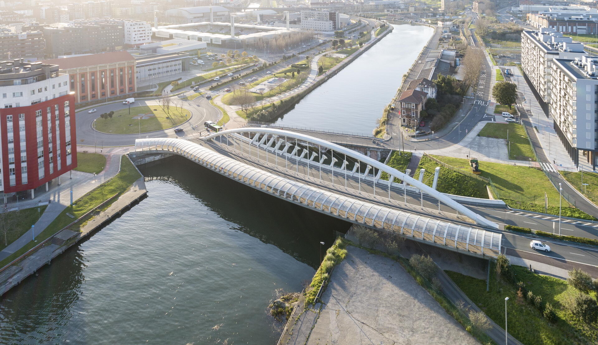
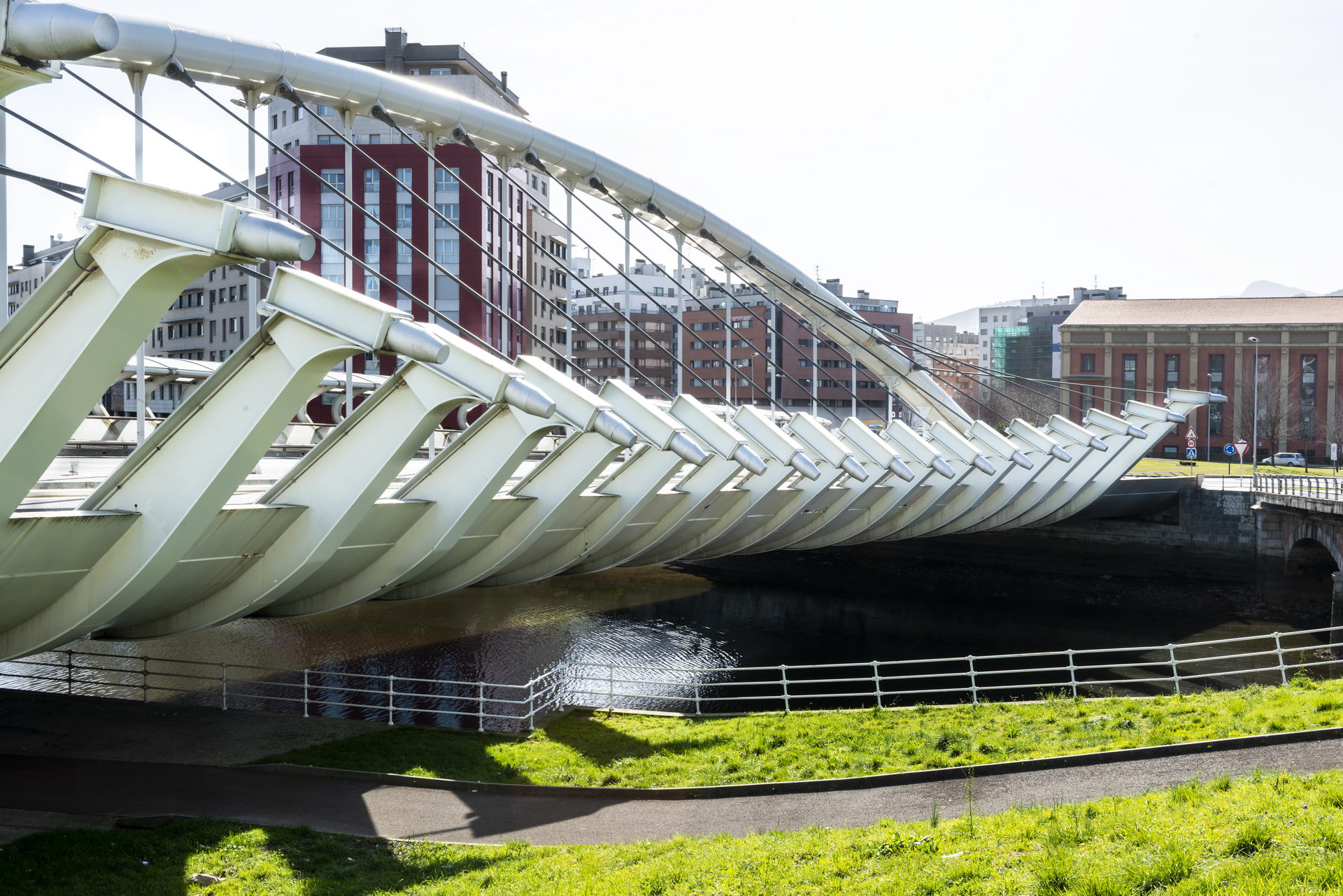
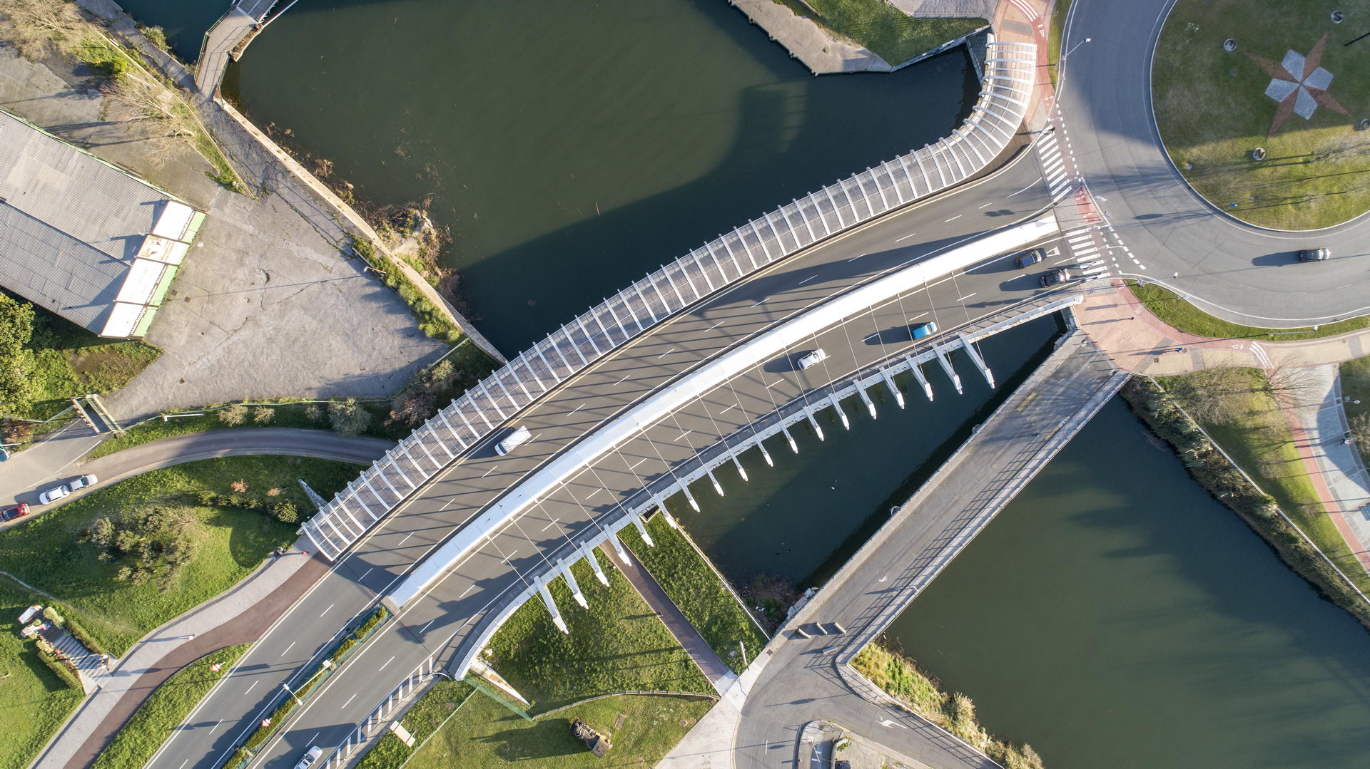
Bridge over the Galindo River. Biscay. Spain. 2008.
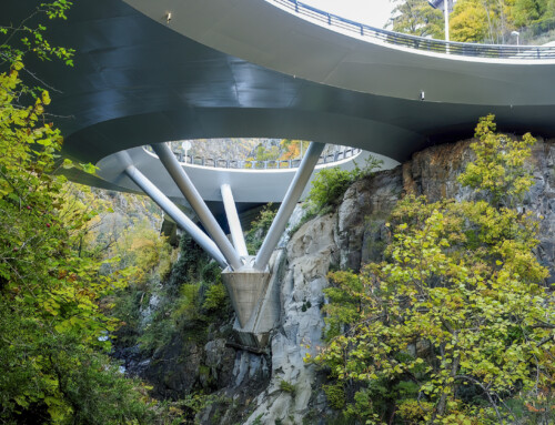
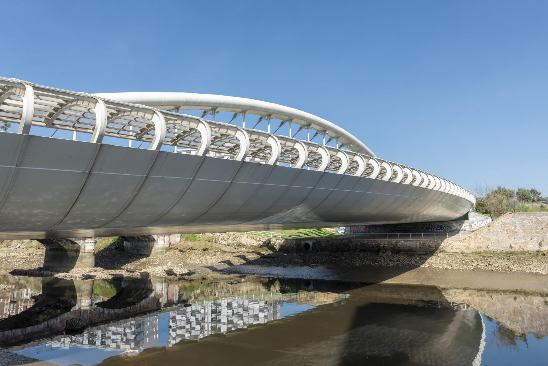
This bridge is arranged over the Galindo River at its mouth in the Nervión estuary with a certain obliquity and jumps cleanly over the river and its side walks without intermediate supports. The layout is very curved in plan, with a radius of 250 meters, with a camber of 5% and a slope of 3%. The bridge is 27 meters wide with a median and two sidewalks on the edges, six meters on the outer edge and only one and a half meters on the inner edge.
Seven possible solutions were tested, all of them with the structure above the platform since the slope is very close to the water level. Three of the solutions were upper lateral beams as an extension of the lower deck. The other four were upper beams or arches located in the median with the condition that the median is not centered.
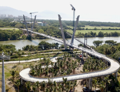
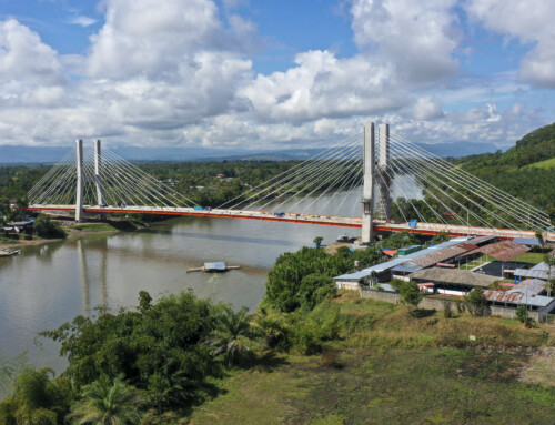
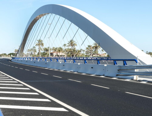
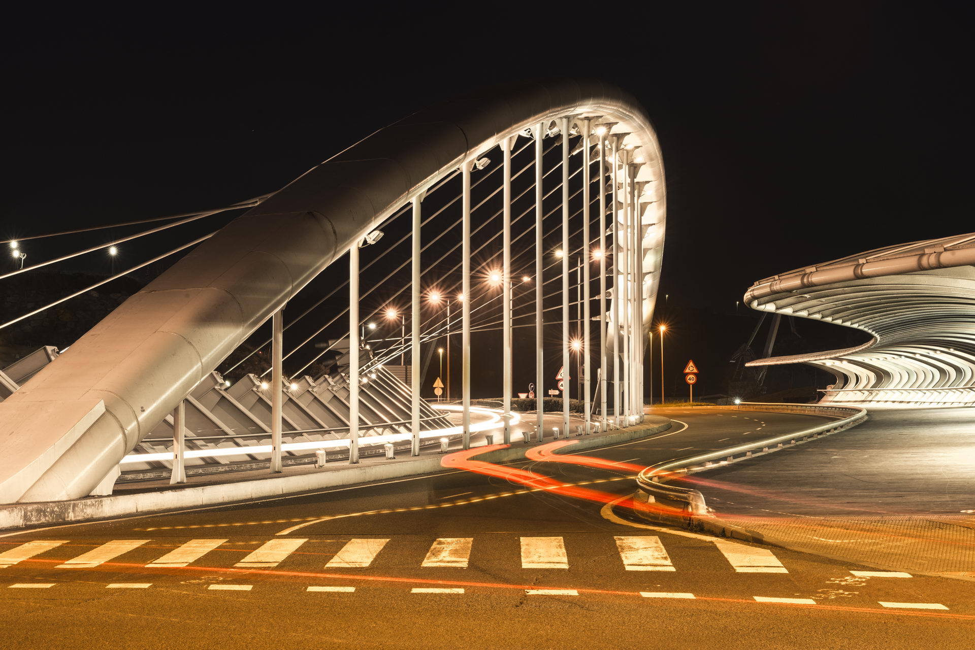
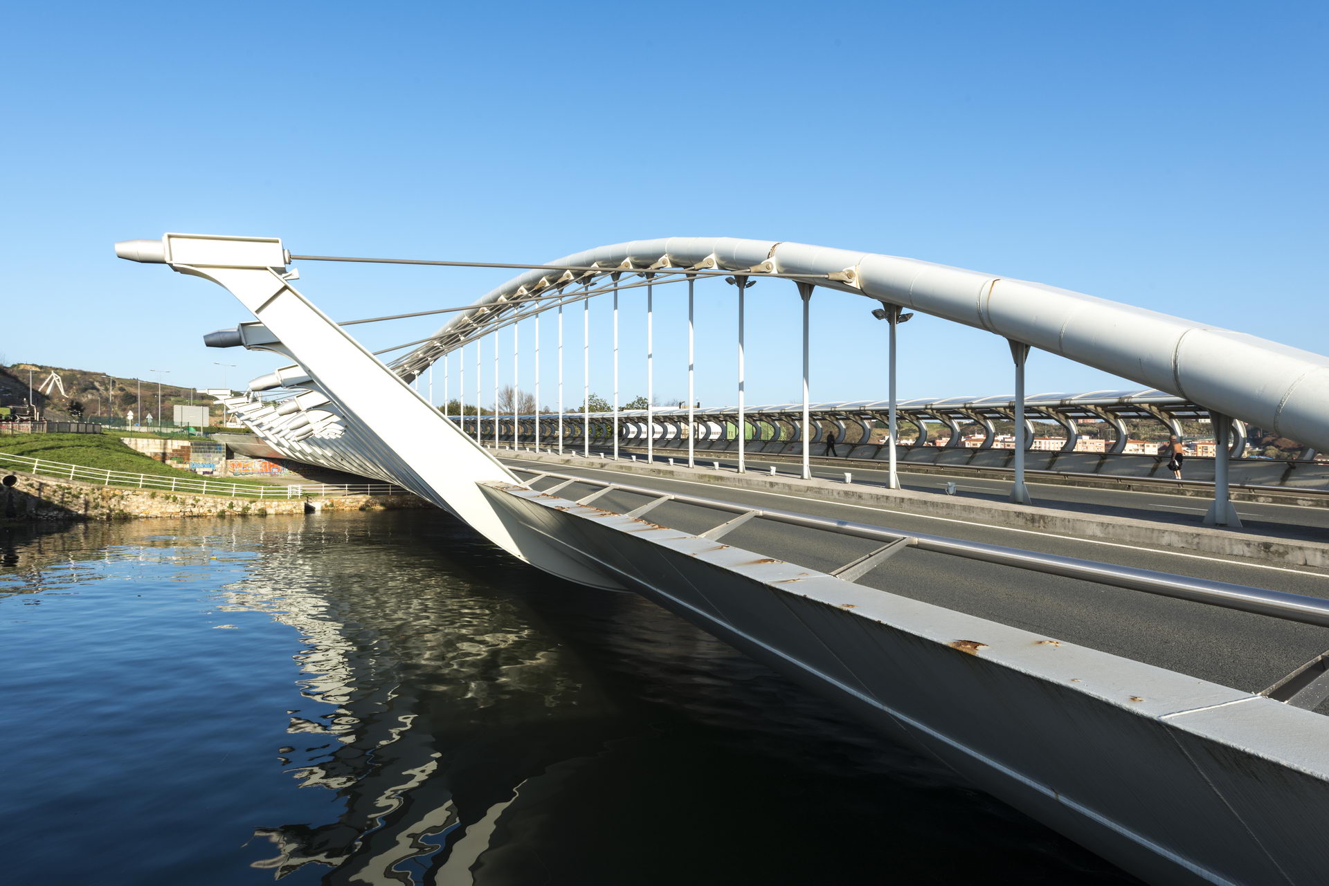
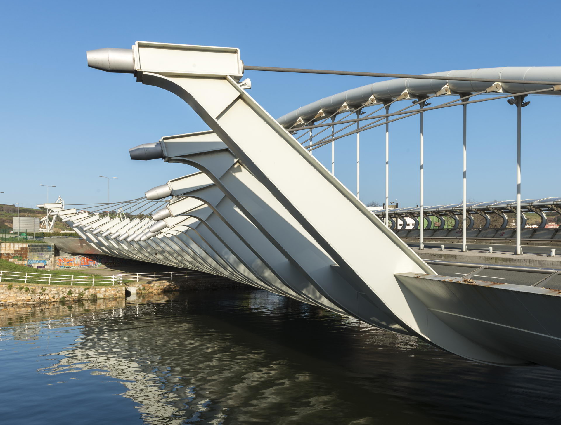
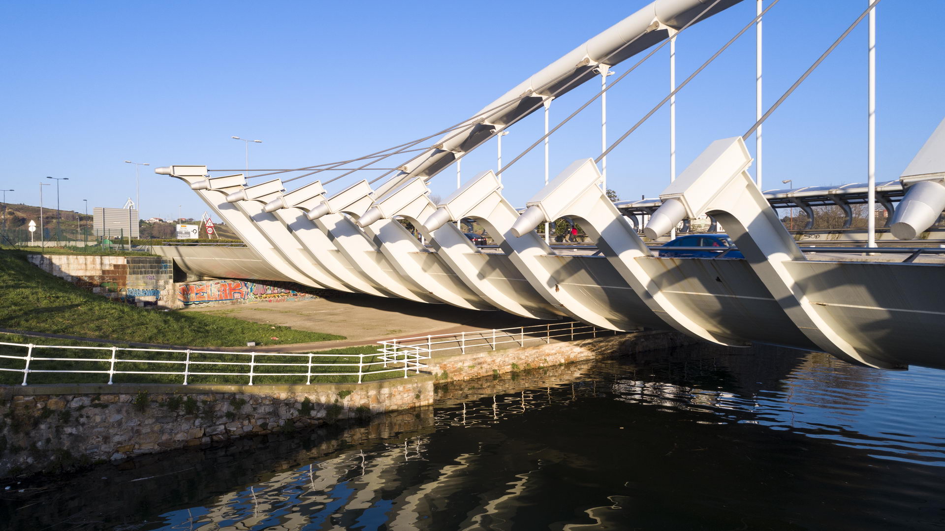
The solution chosen is an arch with a 110-meter span and a 16-meter span with a lower deck. It is the first spatial arch, curved in elevation and curved in plan that exists in the world with a large structure. To counteract the transverse horizontal loads of the arch, due to its curvature in plan, almost horizontal suspenders are anchored in brackets that emerge from the inner edge of the deck. In this way the transverse loads are transformed into torsion in the lower deck.
There is not a single element on the bridge, excluding the deck over the pedestrian walkway, that does not meet a stringent strength requirement. We believe we have turned a sophisticated strength problem into a beautiful new exterior form.
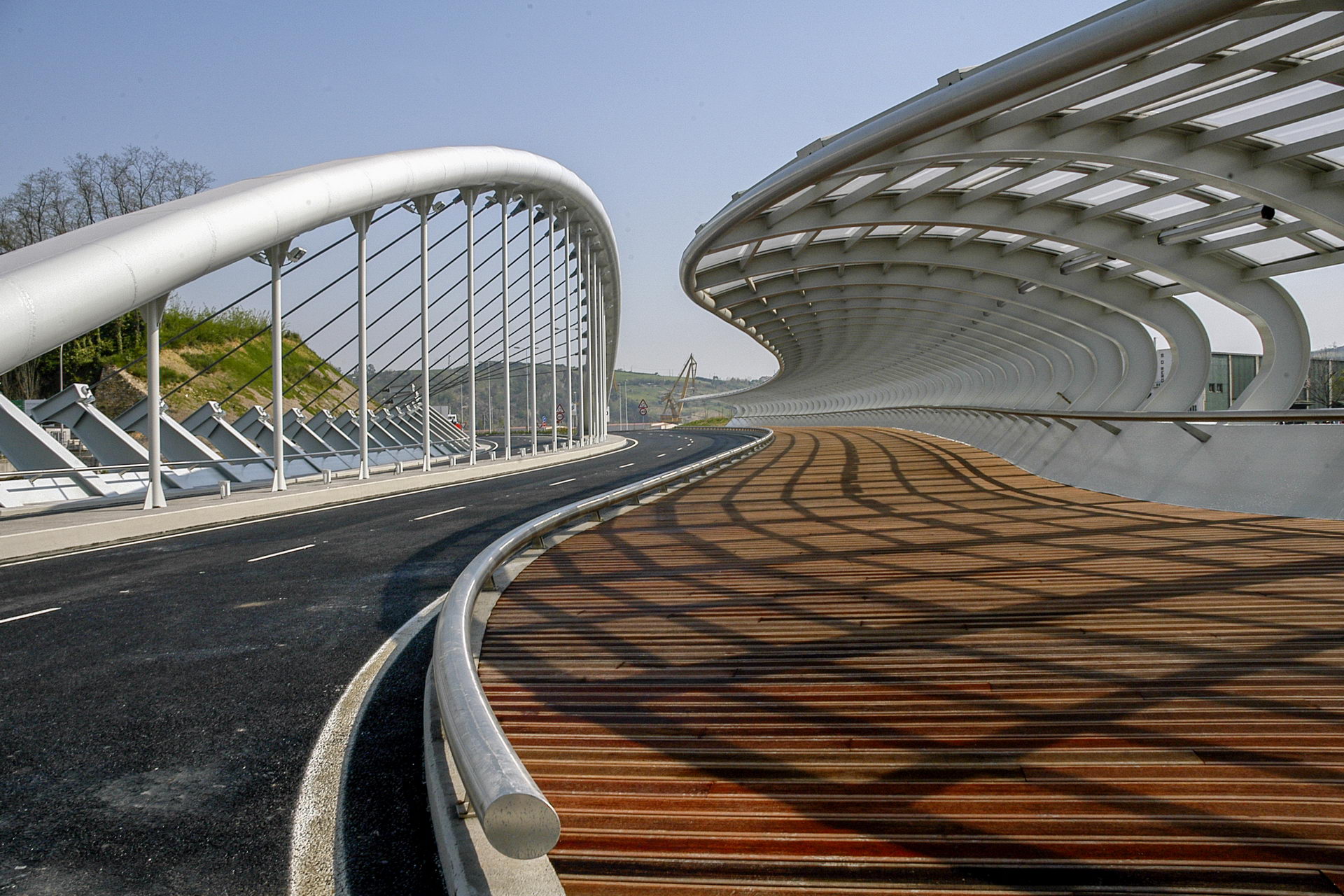
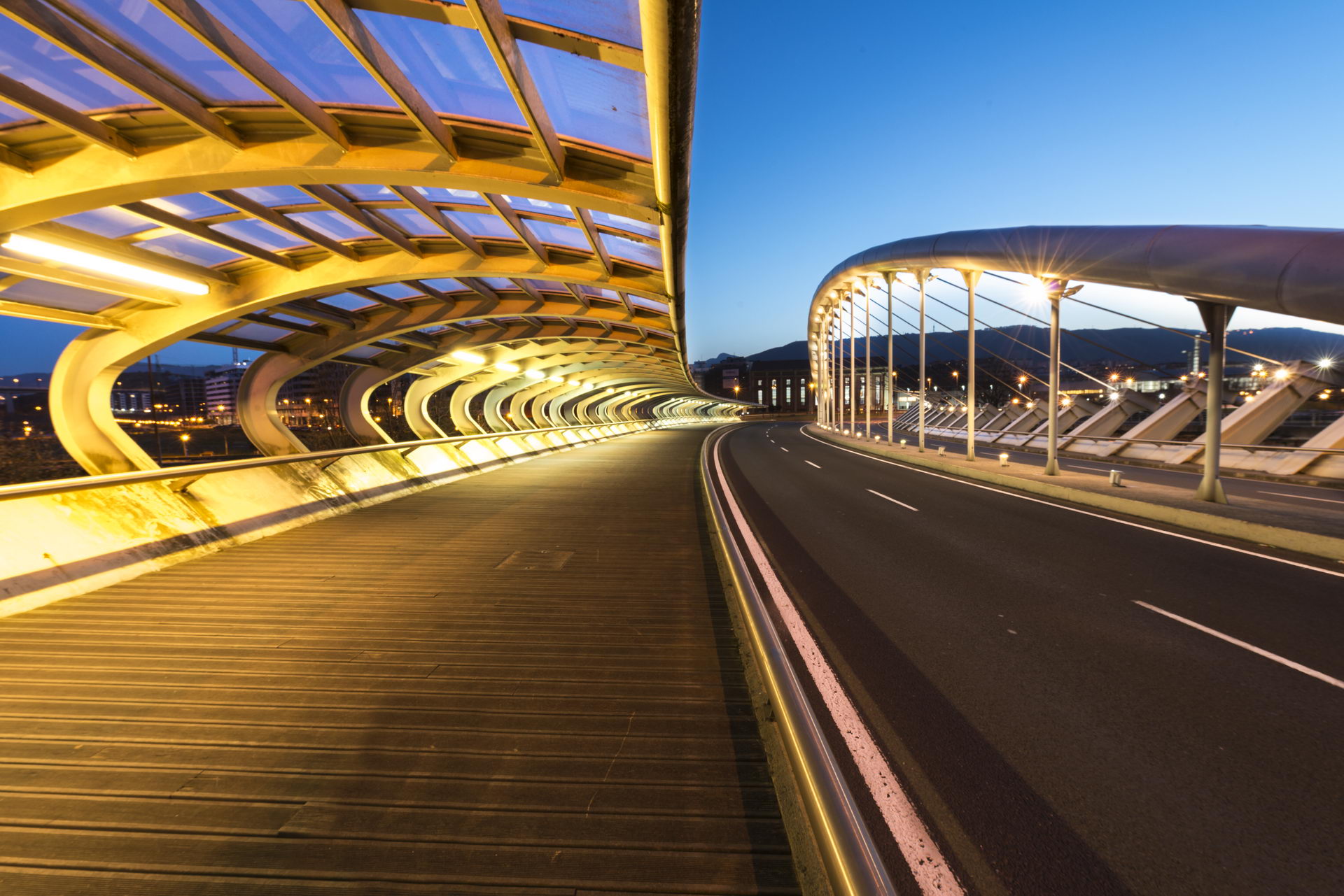
The bridge is biaxially braced on two abutments, is very curved in plan and consists of a metal lintel and a spatial metal arch, not contained in a plane. The lintel is 2 m high and 27.0 m wide, with clearly curved edges. The 6 m wide sidewalk is covered with a non-resistant steel and methacrylate canopy. On the opposite sidewalk, the ribs supporting the transverse suspenders that laterally support the arch are arranged.
The lintel is made entirely of metal with plate thicknesses of 15, 20 and up to 30 mm, distributed around its contour, according to the resistance requirements. It is longitudinally and transversally stiffened. Transversally with diaphragms arranged every 4.4 m and longitudinally with channels for the upper plate and double T’s for the lower plate.
The arch has a 2nd degree parabolic profile in elevation and the ground plan follows the corresponding direction of the deck. It is formed by two tubes of 1,219 mm in diameter and 50.8 mm thick and are joined at the top and bottom by 50 mm thick horizontal plates.
The arch is joined to the deck, at its embedment, by means of 4 longitudinal plates, two per arch, of 80 mm and 90 mm.
The connection of the arch with the cross suspenders and the vertical hangers is made by means of 30 mm thick cross plates that cut the arches completely and connect on one side with the vertical hangers, circular tubes of 193.7 x 19, and on the other side with the active cross suspenders, formed by closed cables of 83 mm diameter. The connection of the arch elements with these transverse plates must be made with full penetration. The arches are straight sections between the vertical plates, which greatly simplifies their execution.
The construction was carried out by means of four temporary supports founded by temporary piles in the river. The deck section was divided into 22-meter long and 5-meter wide pieces that were assembled on the abutments and temporary supports by means of cranes. The already welded deck was used to advance with the following pieces.
The arch was also mounted on four temporary towers on the same vertical of the supports over the river. The pieces were placed by cranes and then welded to the previous piece.
The loading of the pseudo-horizontal stay cables was carried out gradually in three passes from the ends towards the center; towards the end of the operation, the bridge was unstressed. The vertical pendants were loaded by deformation as the shoring of the temporary piers was removed and the active stay cables were loaded.
The “L” abutments are founded on fourteen 1.5 m diameter piles, using a rectangular footing 6.6 m wide by 2.5 m thick and 29.8 m long. Abutment 1 also has a circular wall with a radius of 3 m, separated from the abutment itself and with direct foundations. Both abutments also have a transition slab with the embankment.
On the concave outer edge of the deck, an 8.19 m cantilevered canopy supports a transparent smooth methacrylate roof.